
Speed and passion, quality first
To accelerate innovation and safeguard qualityOur end-to-end service is a highly collaborative and seamless' highway '
Date:2026-11-17
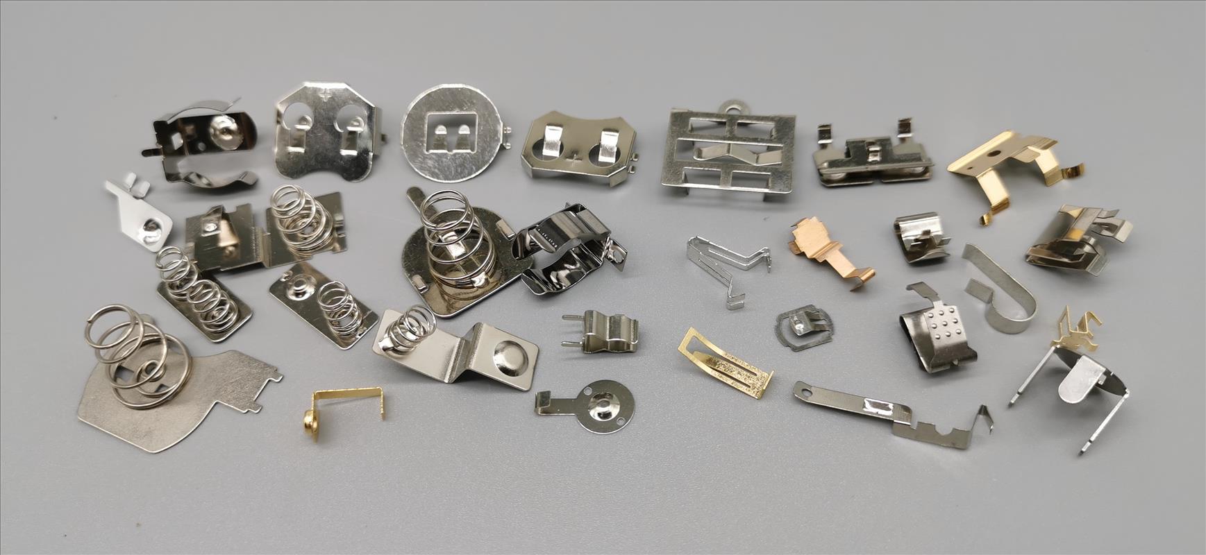 Battery Contact Spring Design: Contact Force, Plating and Cycle Life
Short answer: contact resistance is set by normal force and the surface film, not by the base material's conductivity. A battery contact spring fails for three reasons — too little force, the wrong plating, or stress relaxation at temperature. Specify those three and the rest follows.
A bolted connection and a spring contact are not the same problem. In a spring contact, current passes through a very small real contact area where asperities on two surfaces touch. Total resistance splits into three parts:
| Component | What it is | How to control it |
|---|---|---|
| Constriction resistance | Resistance from current squeezing through tiny contact spots | Increase normal force; increase contact area |
| Film resistance | Oxide, sulfide or plating reaction products on the surface | Plating selection; wipe action on insertion; force high enough to break the film |
| Bulk resistance | Resistance of the spring material itself | Material and thickness selection |
For most battery contacts, film resistance dominates. This is why a brass spring with heavy oxide can measure worse than a steel spring with clean tin — the base material is not the deciding factor.
There is no universal number, and any supplier quoting one without asking about your application is guessing. Force is set by three requirements that must all be satisfied simultaneously:
These pull in opposite directions: more force improves electrical stability but raises insertion effort and accelerates wear on the housing. The correct value is found by vibration and drop testing the assembly, not by copying a number from another product.
Practical approach: start with a force high enough that a 1 m drop test produces no contact interruption, then reduce until the insertion force is acceptable. If the two cannot both be met, change the spring geometry — not the force.
| Plating | Contact resistance | Wear resistance | Cost | Best for |
|---|---|---|---|---|
| Tin | Low initially, rises with oxide growth and thermal cycling | Moderate | Lowest | Consumer devices, low cycle count, dry environments |
| Nickel | Higher than tin or gold, very stable | Good | Low | High-temperature applications, where tin would oxidize |
| Gold over nickel | Lowest and most stable | Excellent | Highest | Signal contacts, low-current, high-reliability, medical |
| Palladium-nickel | Low and stable | Excellent | High | Gold replacement where cost matters, high cycle count |
Two selection traps:
Two independent mechanisms:
Stress relaxation — under sustained deflection at elevated temperature, the spring material gradually takes a permanent set. Force drops even though the spring never "wore out." This is a material property: phosphor bronze relaxes faster than beryllium copper at the same temperature and stress.
Fretting corrosion — small relative motion between contact surfaces repeatedly breaks and reforms the oxide layer. The debris is insulating, so resistance climbs while force appears unchanged. Fretting is driven by vibration amplitude, not by cycle count, which is why a contact can fail in the field long before it reaches its rated insertion cycles.
This is why a cycle-life number quoted without test conditions is not meaningful. "100,000 cycles" means little unless it states stroke, current, temperature and whether the test included vibration.
BOSI stamps battery contact springs and metal spring contacts from phosphor bronze, stainless steel and copper alloys, with:
Reliability validation covers insertion/extraction life, thermal shock, vibration and drop, contact resistance, and shielding effectiveness — so the numbers above are measured, not estimated.
Working on a battery contact that has to survive field vibration? We will review spring geometry and plating before tooling.


 Language
 Your location:


 Official account
 0769-82928019
 E-mail
