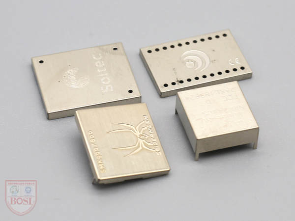
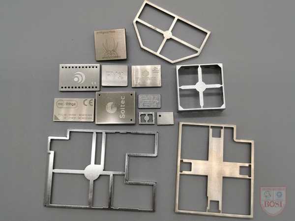
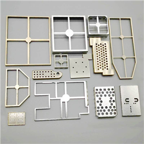
Dongguan Bosi Hardware has been focusing on R&D and production of precision shielding covers for 12 years. How to make the high-quality shielding covers produced by us well mounted on the PCB board is also knowledgeable. The following is a detailed explanation of how to correctly mount the shielding cover element. Manual soldering points for devices.
一. Required equipment:
1 hot air gun, 1 anti-static electric soldering iron, 1 mobile phone board, 1 tweezers, appropriate amount of low melting point solder wire, rosin flux (flux), tin suction wire, appropriate amount of washing water
Specific steps:
1. Turn on the hot air gun, adjust the air volume and temperature to the appropriate position 230 degrees, 4 speed: feel the air volume and temperature of the air duct by hand; observe whether the air duct is unstable with the temperature of the air volume.
2. Observe that the inside of the air duct is reddish. Prevent overheating in the blower.
3. Observe the heat distribution with paper. Find the temperature center.
4. Application and precautions of the tuyere.
5. Blow a resistor with the lowest temperature, and remember the position of the lowest temperature knob that can blow down the resistor.
二. White light digital display heat gun:
1. Adjust the air volume knob so that the steel ball indicated by the air volume is in the middle position.
2. Adjust the temperature control so that the temperature indication is around 380°C.
Note: When the hot air gun is not used for a short time, it should be put into sleep state (if there is a sleep switch on the handle, just press the switch, if there is no switch on the handle, the air nozzle is down to work, and the air nozzle is up to sleep). Turn off the heat gun when not working for 5 minutes.
三. White light 936 digital display constant temperature anti-static soldering iron:
1. The temperature is generally set at 300 °C. If it is used for welding small components, the temperature can be adjusted to a lower temperature. If the components to be welded are large or welded on a large area of metal (such as a large area of copper foil for the ground wire), appropriate Turn up the temperature.
2. The tip of the soldering iron must be white and tinned. If it is gray, it must be treated with a special sponge.
3. Do not press hard on the solder joints when soldering, otherwise the PCB board and the soldering iron tip will be damaged.
4. Do not turn off the power of the soldering iron for a long time to avoid empty burning.
5. Electric soldering irons are generally used in desoldering small components, handling solder joints, handling short circuits, adding soldering, and flying leads.
To desolder the flat pack IC with a hot air gun:
1. Steps to remove the flat package IC:
1) Before removing the components, see the direction of the IC, and do not put them in the opposite direction when reinstalling.
2) Observe whether there are heat-resistant devices (such as liquid crystals, plastic components, BGA ICs with sealant, etc.) beside the IC and on the front and back.
3) Adding appropriate rosin to the IC pins to be removed can make the PCB board pads after the components are removed smooth, otherwise there will be burrs, and it will not be easy to align when re-soldering.
4) The adjusted hot air guns are evenly preheated in an area of about 20 square centimeters around the component (the air nozzle is about 1CM away from the PCB board, and moves at a relatively fast speed in the preheating position, and the temperature of the PCB board does not exceed 130-160 ℃)
A. In addition to the moisture on the PCB, avoid "bubbling" during rework.
B. Avoid stress warping and deformation between the PCB pads caused by the excessive temperature difference between the upper and lower sides of the PCB board due to the rapid heating of one side (above).
C. Reduce the thermal shock of the parts in the welding area due to heating above the PCB board.
D. Prevent the IC next to it from being desoldered and lifted due to uneven heating
E. Circuit board and component heating: The heat gun nozzle is about 1CM away from the IC, and it moves slowly and evenly along the edge of the IC, and gently clamps the diagonal part of the IC with tweezers.
F. If the solder joint has been heated to the melting point, the hand holding the tweezers will feel it for the first time. Be sure to wait until all the solder on the IC pins has melted before carefully placing the component vertically from the board with "zero force". Lift it up, so as to avoid damage to the PCB or IC, and to avoid short circuits of solder left on the PCB board. Heat control is a critical factor in rework, and the solder must melt completely to avoid damaging the pads when the component is removed. At the same time, it is necessary to prevent the board from overheating, and the board should not be twisted due to heating.
(For example: 140℃-160℃ can be selected for preheating and heating at the lower part if possible. The whole process of dismantling the IC does not exceed 250 seconds)
G. After removing the IC, observe whether the solder joints on the PCB are short-circuited. If there is a short-circuit phenomenon, use a hot air gun to heat it again. After the solder at the short-circuit is melted, use tweezers to gently swipe along the short-circuit, and the solder will naturally separate. Try not to deal with it with a soldering iron, because the soldering iron will take away the solder on the PCB board, and there is less solder on the PCB board, which will increase the possibility of virtual soldering. It is not easy to fill tin on the pads of small pins.
四. Steps to install flat IC
1. Observe whether the IC pins to be installed are flat. If there is a short circuit of the IC pin solder, use a solder-absorbing wire to handle it; If the foot is not straight, the crooked part can be corrected with a scalpel.
2. Put an appropriate amount of flux on the pad. If it is heated too much, the IC will float away, and if it is too little, it will not work as it should. And cover and protect the surrounding heat-resistant components.
3. Put the flat IC on the pad in the original direction, and align the IC pins with the PCB pins. When aligning, look down vertically, and align the pins on all four sides. Visually feel the length of the pins on all four sides. Consistent, the pins are straight and not skewed. The sticking phenomenon of rosin when heated can be used to stick to IC.
4. Use a hot air gun to preheat and heat the IC. Note that the hot air gun cannot stop moving during the whole process (if it stops moving, it will cause the local temperature rise to be too high and damage it). While heating, pay attention to observe the IC. If the IC moves again If the phenomenon occurs, adjust it gently with tweezers without stopping the heating. If there is no displacement phenomenon, as long as the solder under the IC pins is melted, it should be found at the first time (if the solder is melted, it will be found that the IC sinks slightly, the rosin has light smoke, the solder is shiny, etc., you can also use tweezers to lightly Lightly touch the small components next to the IC, if the small components next to it move, it means that the solder under the IC pins is also about to melt.) And immediately stop heating. Because the temperature set by the hot air gun is relatively high, the temperature of the IC and PCB board continues to increase. If it is not detected early, the temperature rise will damage the IC or PCB board. So the heating time must not be too long.
5. After the PCB board is cooled, wash and dry the solder joints with Tianna water (or board washing water). Check for soldering and short circuits.
6. If there is virtual soldering, you can use a soldering iron to solder one pin at a time or use a hot air gun to remove the IC and re-solder; if there is a short circuit, wipe the soldering iron tip with a damp heat-resistant sponge The rosin is gently swiped along the pins at the short circuit, which can take away the solder at the short circuit. Or use tin suction wires: pick out four tin suction wires with tweezers and dip them in a small amount of rosin, put them in the short circuit, and press lightly on the tin suction wires with a soldering iron, the solder at the short circuit will melt and stick to the tin suction wires. Clear short circuit.
In addition: You can also use an electric soldering iron to solder the IC. After aligning the IC with the pad, dip the soldering iron in rosin and gently swipe it along the edge of the IC pins; if the IC has a large pin spacing, you can also add Rosin, use a soldering iron to roll a solder ball over all the pins for soldering.
五. Use a hot air gun to desolder the heat-resistant components
1): Remove components:
Generally, plastic components such as cable clips, inline sockets, sockets, SIM card sockets, battery contacts, tail plugs and other plastic components are easily deformed by heat. If they are indeed broken, you may as well remove them like desoldering ordinary ICs. If you want to remove It is still in good condition and needs to be handled with care. There is a rotating air hot air gun with uniform air volume and heat, which generally does not damage plastic components. If you use an ordinary air gun, you can consider putting the PCB board on the edge of the table, use the air gun to heat the front and back of the component from the bottom up, transfer the heat to the top through the PCB board, and remove it when the solder melts; A waste chip of the same size is covered on the heating element, and then the edge of the chip is heated with an air gun, and the plastic element can be removed after the solder below melts.
2): Install components:
Arrange the pads on the PCB board, dip a proper amount of flux on the component pins and place them next to the pads, in order to let them get a little hot. Heat the PCB board with a hot air gun. When the solder on the board is bright, it means that it has melted. Quickly place the components on the pads accurately. At this time, the air gun cannot stop moving and heating. Use tweezers to adjust the position of the components in a short time. Immediately withdraw the air gun. This method is also suitable for installing power amplifiers and power ICs with large heat dissipation areas.
Some devices can be easily soldered with a soldering iron (such as a SIM card holder), so don't use an air gun.
六. Desoldering small components such as RC transistors
1): Remove components:
A. Add an appropriate amount of rosin to the component, gently clamp the component with tweezers, and use a heat gun to move and heat the small component evenly (same as desoldering IC), and the hand holding the tweezers feels that the solder has melted, and the component can be removed.
B. Use a soldering iron to add an appropriate amount of solder to the component. The soldering tin covers the solder joints on both sides of the component. Place the tip of the soldering iron flat on the side of the component, so that the newly added solder is in a molten state, and the component can be removed. If the component is large, you can add more tin to the solder joints of the component, clamp the component with tweezers, and quickly heat the two solder joints with a soldering iron in turn until both solder joints are in a melted state, which can be removed.
2): Install components:
A. Add an appropriate amount of rosin to the component, gently clamp the component with tweezers, align the component with the solder joints, use a hot air gun to move and heat the small component evenly, and release the tweezers after the solder under the component is melted. (You can also place the components and heat them, and then touch the components with tweezers after the solder melts to align them.)
B. Lightly clamp the component with tweezers, and click on each pin of the component with a soldering iron to solder it. If there is less solder on the solder joint, you can place a small tin bead on the tip of the soldering iron and add it to the pin of the component.
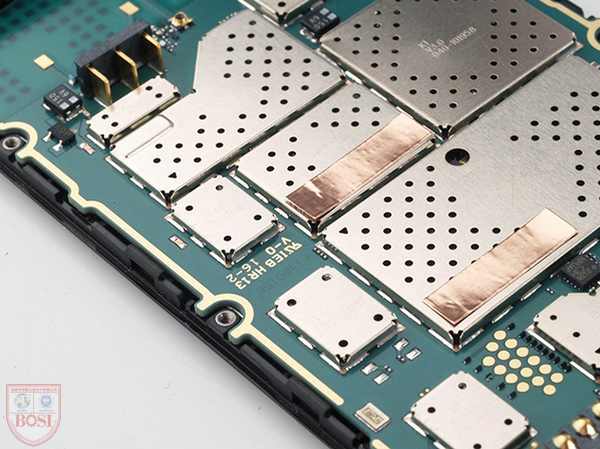
七. Use a hot air gun to desolder the shield:
1): Remove the shielding cover:
Use a clamp to clamp the PCB board, clamp the shield with tweezers, heat the entire shield with a hot air gun, and lift it vertically after the solder melts. Because removing the shielding cover requires a high temperature, other components on the PCB will also be loose. When the shielding cover is removed, the main board cannot move, so as not to vibrate and displace the components on the board. When removing the shielding cover, lift it vertically to avoid Components inside the shield are displaced. You can also lift up the three sides of the shielding cover first, fold it back and forth a few times after cooling, and break the last side to remove the shielding cover.
2): Install the shielding cover:
Put the shielding cover on the PCB board and heat it around with an air gun until the solder melts. You can also use a soldering iron to select a few spots to solder on the PCB.
八. Add welding virtual welding components:
1): Welding with air gun
Add a little rosin to the parts of the PCB board that need to be soldered, and use an air gun to heat evenly until the solder in the soldered parts melts. You can also use tweezers to gently touch the components that are suspected to be soldered when the solder is melted. Strengthen the welding effect.
2): Use an electric soldering iron to weld
It is used for soldering a small number of components. If it is soldering IC, you can add a small amount of rosin to the IC pins, and use a smooth soldering iron tip to solder the pins one by one. Be sure to wipe off any residual tin on the tip of the soldering iron, otherwise it will short out the pins. If it is small components such as soldering resistors, triodes, etc., directly dip the tip of a soldering iron into rosin and solder the pins of the components. Sometimes in order to increase the welding strength, a little solder can also be added to the component pins.
九. Required equipment:
1 hot air gun, 1 anti-static electric soldering iron, 1 mobile phone board, 1 tweezers, appropriate amount of low melting point solder wire, rosin flux (flux), tin suction wire, appropriate amount of washing water
Specific steps:
1. Turn on the hot air gun, adjust the air volume and temperature to the appropriate position 230 degrees, 4 speed: feel the air volume and temperature of the air duct by hand; observe whether the air duct is unstable with the temperature of the air volume.
2. Observe that the inside of the air duct is reddish. Prevent overheating in the blower.
3. Observe the heat distribution with paper. Find the temperature center.
4. Application and precautions of the tuyere.
5. Blow a resistor with the lowest temperature, and remember the position of the lowest temperature knob that can blow down the resistor.
十. White light digital heat gun:
1. Adjust the air volume knob so that the steel ball indicated by the air volume is in the middle position.
2. Adjust the temperature control so that the temperature indication is around 380°C.
Note: When the hot air gun is not used for a short time, it should be put into sleep state (if there is a sleep switch on the handle, just press the switch, if there is no switch on the handle, the air nozzle is down to work, and the air nozzle is up to sleep). Turn off the heat gun when not working for 5 minutes.
十一. White light 936 digital display constant temperature anti-static soldering iron:
1. The temperature is generally set at 300 °C. If it is used for welding small components, the temperature can be adjusted to a lower temperature. If the components to be welded are large or welded on a large area of metal (such as a large area of copper foil for the ground wire), appropriate Turn up the temperature.
2. The tip of the soldering iron must be white and tinned. If it is gray, it must be treated with a special sponge.
3. Do not press hard on the solder joints when soldering, otherwise the PCB board and the soldering iron tip will be damaged.
4. Do not turn off the power of the soldering iron for a long time to avoid empty burning.
5. Electric soldering irons are generally used in desoldering small components, handling solder joints, handling short circuits, adding soldering, and flying leads.
十二. use the hot air gun to desolder the flat package IC:
1): Steps to remove the flat package IC:
A. Before removing the components, see the direction of the IC, and do not put them in the opposite direction when reinstalling.
B. Observe whether there are heat-resistant devices (such as liquid crystals, plastic components, BGA ICs with sealant, etc.) beside the IC and on the front and back.
C. Adding appropriate rosin to the IC pins to be removed can make the PCB board pads after the components are removed smooth, otherwise there will be burrs, and it will not be easy to align when re-soldering.
D. The adjusted hot air guns are evenly preheated in an area of about 20 square centimeters around the component (the air nozzle is about 1CM away from the PCB board, and moves at a relatively fast speed in the preheating position, and the temperature of the PCB board does not exceed 130-160 ℃)
1) In addition to the moisture on the PCB, avoid "bubbling" during rework.
2) Avoid stress warping and deformation between the PCB pads caused by the excessive temperature difference between the upper and lower sides of the PCB board due to the rapid heating of one side (above).
3) Reduce the thermal shock of the parts in the welding area due to heating above the PCB board.
4) Prevent the IC next to it from being desoldered and lifted due to uneven heating
5) Circuit board and component heating: The heat gun nozzle is about 1CM away from the IC, and it moves slowly and evenly along the edge of the IC, and gently clamps the diagonal part of the IC with tweezers.
6) If the solder joint has been heated to the melting point, the hand holding the tweezers will feel it for the first time. Be sure to wait until all the solder on the IC pins has melted before carefully placing the component vertically from the board with "zero force". Lift it up, so as to avoid damage to the PCB or IC, and to avoid short circuits of solder left on the PCB board. Heat control is a critical factor in rework, and the solder must melt completely to avoid damaging the pads when the component is removed. At the same time, it is necessary to prevent the board from overheating, and the board should not be twisted due to heating.
(For example: 140℃-160℃ can be selected for preheating and heating at the lower part if possible. The whole process of dismantling the IC does not exceed 250 seconds)
7) After removing the IC, observe whether the solder joints on the PCB are short-circuited. If there is a short-circuit phenomenon, use a hot air gun to heat it again. After the solder at the short-circuit is melted, use tweezers to gently swipe along the short-circuit, and the solder will naturally separate. Try not to deal with it with a soldering iron, because the soldering iron will take away the solder on the PCB board, and there is less solder on the PCB board, which will increase the possibility of virtual soldering. It is not easy to fill tin on the pads of small pins.
十三. Steps to install flat IC
1. Observe whether the IC pins to be installed are flat. If there is a short circuit of the IC pin solder, use a solder-absorbing wire to handle it; If the foot is not straight, the crooked part can be corrected with a scalpel.
2. Put an appropriate amount of flux on the pad. If it is heated too much, the IC will float away, and if it is too little, it will not work as it should. And cover and protect the surrounding heat-resistant components.
3. Put the flat IC on the pad in the original direction, and align the IC pins with the PCB pins. When aligning, look down vertically, and align the pins on all four sides. Visually feel the length of the pins on all four sides. Consistent, the pins are straight and not skewed. The sticking phenomenon of rosin when heated can be used to stick to IC.
4. Use a hot air gun to preheat and heat the IC. Note that the hot air gun cannot stop moving during the whole process (if it stops moving, it will cause the local temperature rise to be too high and damage it). While heating, pay attention to observe the IC. If the IC moves again If the phenomenon occurs, adjust it gently with tweezers without stopping the heating. If there is no displacement phenomenon, as long as the solder under the IC pins is melted, it should be found at the first time (if the solder is melted, it will be found that the IC sinks slightly, the rosin has light smoke, the solder is shiny, etc., you can also use tweezers to lightly Lightly touch the small components next to the IC, if the small components next to it move, it means that the solder under the IC pins is also about to melt.) And immediately stop heating. Because the temperature set by the hot air gun is relatively high, the temperature of the IC and PCB board continues to increase. If it is not detected early, the temperature rise will damage the IC or PCB board. So the heating time must not be too long.
5. After the PCB board is cooled, wash and dry the solder joints with Tianna water (or board washing water). Check for soldering and short circuits.
6. If there is virtual soldering, you can use a soldering iron to solder one pin at a time or use a hot air gun to remove the IC and re-solder; if there is a short circuit, wipe the soldering iron tip with a damp heat-resistant sponge The rosin is gently swiped along the pins at the short circuit, which can take away the solder at the short circuit. Or use tin suction wires: pick out four tin suction wires with tweezers and dip them in a small amount of rosin, put them in the short circuit, and press lightly on the tin suction wires with a soldering iron, the solder at the short circuit will melt and stick to the tin suction wires. Clear short circuit.
In addition: You can also use an electric soldering iron to solder the IC. After aligning the IC with the pad, dip the soldering iron in rosin and gently swipe it along the edge of the IC pins; if the IC has a large pin spacing, you can also add Rosin, use a soldering iron to roll a solder ball over all the pins for soldering.
十四. Use a hot air gun to desolder the heat-resistant components
1): Remove components:
Generally, plastic components such as cable clips, inline sockets, sockets, SIM card sockets, battery contacts, tail plugs and other plastic components are easily deformed by heat. If they are indeed broken, you may as well remove them like desoldering ordinary ICs. If you want to remove It is still in good condition and needs to be handled with care. There is a rotating air hot air gun with uniform air volume and heat, which generally does not damage plastic components. If you use an ordinary air gun, you can consider putting the PCB board on the edge of the table, using

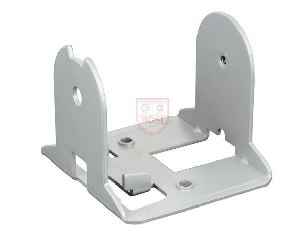
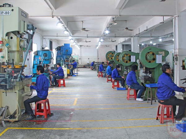
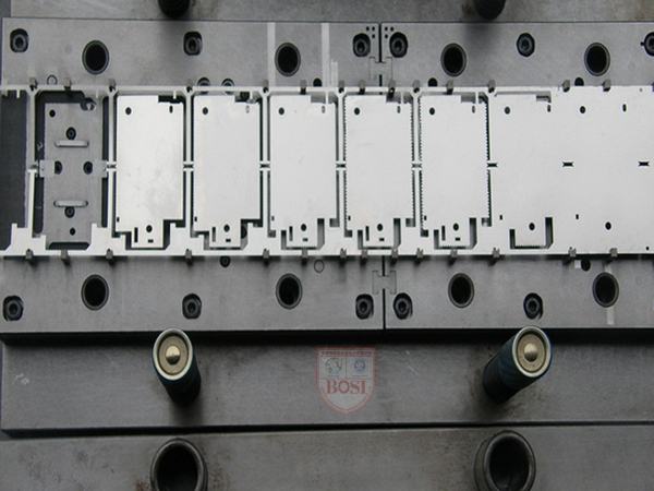
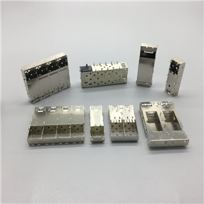
BOSI shielding cover has 12 years of foreign trade export experience, the quality is guaranteed, and the craftsmanship has reached the industry-leading level! We only customize high-quality metal stamping parts, the company has passed ISO9001: 2015, IATF 16949 certification, the products are favored by new and old customers! Choosing Bosi is equal to choosing high quality! At present, Bosi has more than 200 kinds of shielding case samples and molds, covering various specifications of the shielding case required by users with a high probability, saving the time and cost of mold opening and proofing for customers, you only need to provide the size, we will Get a quick quote for you and provide you with a sample drawing of a similar shield.
If you intend to purchase shielding cover, pls kindly contact us,thanks.